Principle of Operation
Manometers derive pressure by the combination of a height differential of a liquid column and the density of the fluid within the liquid column. The U type manometer, which is considered as a primary pressure standard, derives pressure utilizing the following equation:
P = P2 – P1 = hw ρg
Where:
P = Differential pressure
P1 = Pressure applied to the low pressure connection
P2 = Pressure applied to the high pressure connection
hw = is the height differential of the liquid columns between the two legs of the manometer
ρ = mass density of the fluid within the columns
g = acceleration of gravity
5.1 Types of Manometers
5.1.1 U Tube Manometers
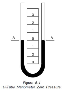
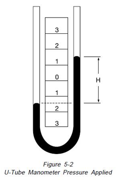
“The principle of operation of the U type manometer is shown on Figure 5-1. It is simply a glass tube bent to form the letter U and partially filled with some liquid. With both legs of the instrument open to atmosphere or subjected to the same pressure, Figure 5-1, the liquid maintains exactly the same level or zero reference. As illustrated on
Figure 5-2, if a pressure is applied to the left side of the instrument, the fluid recedes in the left leg and raises in the right leg. The fluid moves until the unit weight of the fluid as indicated by “H” exactly balances the pressure. This is known as hydrostatic balance. The height of fluid from one surface to the other is the actual height of fluid opposing the pressure.
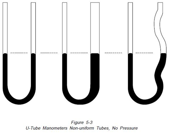
The pressure is always the height of fluid from one surface to the other regardless of the shape or size of the tubes, as illustrated in Figure 5-3.
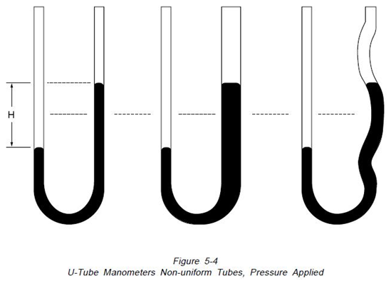
The left hand manometer has a uniform tube, the center one has an enlarged leg and the right one has an irregular leg. Manometers at the top are open to atmosphere on both legs so the indicating fluid level in both legs is the same. Imposing an identical pressure on the left leg of each manometer, as shown on Figure 5-4, causes the fluid level in each manometer to change. Because of the variations in volume of the manometer legs, the distances moved by the fluid columns are different. However, “H” the total distance between the fluid levels, remains identical in the three manometers”15.
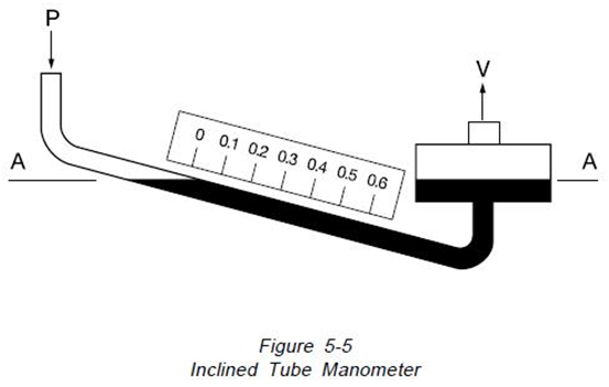
5.1.2 Inclined Tube Manometers
“Many applications require accurate measurements of low pressure such as drafts and very low differentials. To better handle these applications, the manometer is arranged with the indicating tube inclined, as in Figure 5-5, providing for better resolution. This arrangement can allow 12” of scale length to represent 1″ of vertical height. With scale subdivisions, a pressure of 0.00036 PSI (1/100 inch of water) can be read”15.
5.1.3 Well Type Manometers
The well type manometer is illustrated on Figure 5-6. In this design, the pressure is applied to a fluid well attached to a single indicating tube. As the fluid moves down in the well, the fluid is displaced into the smaller indicating leg of the manometer. This permits direct reading on a single scale.
The well type manometer utilizes the principle of volume balance wherein the fluid displaced from the well is equal to the added fluid in the smaller indicating column. The well area and the internal diameter of the indicating type must be carefully controlled to insure the accuracy of the instrument.
The well type manometer does not fulfill the requirements of a primary standard as described in paragraph 1.5 and can be considered as one form of a secondary standard.
5.2 Intrinsic Correction Factors
5.2.1 Fluid Density Correction
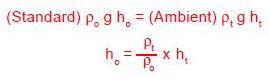
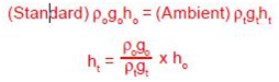
Manometers indicate the correct pressure at only one temperature. This is because the indicating fluid density changes with temperature. If water is the indicating fluid, an inch scale indicates one inch of water at 4°C only. On the same scale mercury indicates one inch of mercury at 0°C only. If a reading using water or mercury is taken at 20°C then the reading is not an accurate reading. The error introduced is about 0.4% of reading for mercury and about 0.2% of reading for water. Since manometers are used at temperatures above and below the standard temperature, corrections are needed. A simple way for correcting for density changes is to ratio the densities.
Where:
ho = Corrected height of the indicating fluid to standard temperature
ht = Height of the indicating fluid at the temperature when read
ρo = Density of the indicating fluid at standard temperature
ρt = Density of the indicating fluid when read
Using this method is very accurate, when density/ temperature relations are known. Data is readily available for water and mercury.
Density (g/cm3) as a function of temperature (°C) for mercury:
= 13.556786 [1 – 0.0001818 (T – 15.5556)]
Density ( g/cm3) as a function of temperature for water:
= 0.9998395639 + 6.798299989 x 10⁻⁵ (T)
– 9.10602556X10⁻⁶ (T2) + 1.005272999 x
10-7 (T3) – 1.126713526 x 10⁻⁹(T4) +
6.591795606 x 10⁻¹² (T5)
For other fluids, manometer scales and fluid densities may be formulated to read inches of water or mercury at a set temperature. The manometer still only reads correct at one temperature, and for precise work the temperature corrections cannot be overlooked.
5.2.2 Gravity Correction
The need for gravity corrections arises because gravity at the location of the instrument governs the weight of the liquid column. Like the temperature correction, gravity correction is a ratio.
go = International Standard Gravity(980.665
Gals.)
gt = Gravity at the instrument’s location (In
Gals.)
A 10° change in latitude at sea level will introduce approximately 0.1% error in reading.
At the Equator (0° Latitude) the error is approximately 0.25%. An increase in elevation of 5000 feet (1524 m) will introduce an error of approximately 0.05%.
For precise work you must have the value of the gravity measured at the instrument location. Gravity values have been determined by the U.S. Coast and Geodetic Survey at many points in the United States. Using these values, the U.S. Geodetic Survey may interpolate and obtain a gravity value sufficient for most work. To obtain a gravity report, the instruments latitude, longitude and elevation are needed. Similar agencies are available in countries outside the United States. Contact local authorities for the agency and procedures to determine local gravity.
Where a high degree of accuracy is not necessary and values of local gravity have not been determined, calculations for differences in local gravity can be obtained. Gravity at a known latitude is:
Gx= 980.616 [1 – 0.0026373 cos(2x) + 0.0000059cos2(2x)]
Where:
Gx = gravity value at latitude x, sea level (cm/sec2)
x = latitude (degrees)
The relationship for inland values of gravity at elevations above sea level is:
Gt = Gx – 0.000094H + 0.00003408(H-H1)(cm/sec2)
Where:
H = Elevation (feet) above mean sea level
H1 = Average elevation (feet) of the general terrain within a radius of 100 miles of the point
5.2.3 Pressure Medium Head Correction
Commonly, a differential pressure is measured by the height of the fluid column. Actually the differential pressure, measured by the indicating fluid height, is the difference between the density of the fluid column and the density of equal height of the pressure medium.
The relationship is:
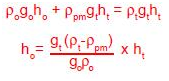
Where:
ρpm = density of the pressure medium
The significance of the pressure medium correction effect on the manometer reading varies with the indicating fluid and pressure medium. Whether this correction is necessary depends upon the user’s accuracy requirements. The most common pressure medium is air. Not correcting for air over water yields an error of 0.12% (using the density of air as 0.0012 g/cm3). In precise work, air density can be determined exactly knowing the temperature, pressure and relative humidity of the air. The correction for air over mercury is extremely small (0.008% error) and there for may usually be ignored. Another application, often used in flow applications, is water over mercury. The pressure medium correction in this situation is mandatory. An error of 7.4% is introduced if the correction is not applied. In many instances manometer scales can be designed with this correction built-in.
5.2.4 Scale Corrections
Another factor governing manometer’s accuracy is the scale. As with indicating fluids, temperature changes affect the scale. At higher temperatures the scale will expand and graduations will be further apart. The opposite effect will occur at lower temperatures. All Meriam scales are fabricated at a temperature of 22°C (71.6°F). A 10°C shift in temperature from that temperature will induce an error in the reading of about 0.023% in an aluminum scale. All Meriam scales are made of aluminum.
ho = ht [1 + a(T – To)]
Where:
á = Coefficient of linear expansion for the scale material (0.0000232/°C for aluminum)
T = the temperature when the manometer was read To = temperature when the scale was manufactured
5.2.5 Compressibility, Absorbed Gases and Capillary Considerations
Compressibility of indicating fluids is negligible except in a few applications. For compressibility to have an effect, the manometer must be used in measuring high differential pressures.
At high differential pressures the fluid shrinkage (Increase in density) may begin to be resolvable on the manometer. At 250 PSI the density of water changes approximately 0.1%.
Depending upon accuracy requirements compressibility may or may not be critical. The relationship between pressure and density of water is as follows:
ρ= 0.00000364 p + 0.9999898956
Where:
ρ= density of water(g/cm3) at 4°C and pressure p
p = pressure in PSIA
Since the need to correct is very rare, other indicating fluid’s compressibilities have not been determined. Mercury’s compressibility is negligible.
Absorbed gases are those gases found dissolved in a liquid. The presence of dissolved gases decreases the density of the liquid. Air is a commonly dissolved gas that is absorbed by most manometer fluids. The density error of water fully saturated with air is 0.00004% at 20°C. The effect is variable and requires consideration for each gas in contact with a particular fluid. Mercury is one exception in which absorbed gases are not found. This makes mercury an excellent manometer fluid in vacuum and absolute pressure applications.
Capillary effects occur due to the surface tension or wetting characteristics between the liquid and the glass tube. As a result of surface tension, most fluids form a convex meniscus.
Mercury is the only fluid that does not wet the glass, and consequently forms a concave meniscus. For consistent results, you must always observe the fluid meniscus in the same way, whether convex or concave. To help reduce the effects of surface tension, manometers should be designed with large bore tubes. This flattens the meniscus, making it easier to read. A large bore tube also helps fluid drainage. The larger the bore the smaller the time lag while drainage occurs. Another controlling factor is the accumulation of corrosion and dirt on the liquid surface. The presence of foreign material changes the shape of the meniscus. With mercury, it helps to tap or vibrate the tube to reduce error in the readings. a final note to capillary effects is the addition of a wetting agent to the manometer fluid. Adding the wetting agent helps in obtaining a symmetrical meniscus.
5.2.6 Parallax (Readability)
In order to achieve consistent results, the level of the meniscus on a manometer must be read with the eyes level to the meniscus. Placing the eyes level with the meniscus eliminates reading distortions caused by angle of reading,parallax, etc. If a mirror back is available, it will aid in placing the operators eyes in the proper position before taking a reading.
To duplicate the factory calibration procedure, read the lowest indicated liquid level as measured by the hairline at which the original zero was set.
Source: Ametek