Brinell Hardness Testing
The Brinell hardness test method as used to determine Brinell hardness is defined in ASTM E10. Most commonly it is used to test materials that have a structure that is too coarse or that have a surface that is too rough to be tested using another test method, e.g., castings and forgings. Brinell testing often use a very high test load (3000 kgf) and a 10mm wide indenter so that the resulting indentation averages out most surface and sub-surface inconsistencies.
The Brinell method applies a predetermined test load (F) to a carbide ball of fixed diameter (D) which is held for a predetermined time period and then removed. The resulting impression is measured across at least two diameters – usually at right angles to each other and these result averaged (d). A chart is then used to convert the averaged diameter measurement to a Brinell hardness number. Test forces range from 500 to 3000 kgf.
A Brinell hardness result measures the permanent width of indentation produced by a carbide indenter applied to a test specimen at a given load, for a given length of time. Typically, an indentation is made with a Brinell hardness testing machine and then measured for indentation diameter in a second step with a specially designed Brinell microscope or optical system. The resulting measurement is converted to a Brinell value using the Brinell formula or a conversion chart based on the formula. Most typically, a Brinell test will use 3000 kgf load with a 10mm ball. If the sample material is aluminum, the test is most frequently performed with a 500 kgf load and 10mm ball. Brinell test loads can range from 3000 kgf down to 1 kgf. Ball indenter diameters can range from 10mm to 1mm. Generally, the lower loads and ball diameters are used for convenience in “combination” testers, like Rockwell units, that have a small load capacity. The test standard specifies a time of 10 to 15 seconds, although shorter times can be used if it is known that the shorter time does not affect the result. There are other conditions that must be met for testing on a round specimen, spacing of indentations, minimum thickness of test specimens, etc.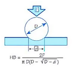
Test Method Illustration
D = Ball diameter
d = impression diameter
F = load
HB = Brinell result
Typically the greatest source of error in Brinell testing is the measurement of the indentation. Due to disparities in operators making the measurements, the results will vary even under perfect conditions. Less than perfect conditions can cause the variation to increase greatly. Frequently the test surface is prepared with a grinder to remove surface conditions. The jagged edge makes interpretation of the indentation difficult. Furthermore, when operators know the specifications limits for rejects, they may often be influenced to see the measurements in a way that increases the percentage of “good” tests and less re-testing.
Two types of technological remedies for countering Brinell measurement error problems have been developed over the years. Automatic optical Brinell scopes use computers and image analysis to read the indentations in a consistent manner. This standardization helps eliminate operator subjectivity so operators are less-prone to automatically view in-tolerance results when the sample’s result may be out-of-tolerance.
Brinell units, according to ASTM E103, measure the samples using Brinell hardness parameters together with a Rockwell hardness method. This method provides the most repeatable results (and greater speed) since the vagaries of optical interpretations are removed through the use of an automatic mechanical depth measurement. Using this method, however, results may not be strictly consistent with Brinell results due to the different test methods – an offset to the results may be required for some materials. It is easy to establish the correct values in those cases where this may be a problem.
Source by: AMETEK