Ametek Deadweight Testers
AMETEK creates an extensive line of both pneumatic and hydraulic deadweight gauges and deadweight testers for both laboratory and field portable applications. This chapter well describes the unique features of the AMETEK instruments, the features of each tester, operating procedures and care of the testers.
4.1 Deadweight Testers and Deadweight Gauges
All deadweight testers and deadweight gauges are primary pressure standards. These instruments are one of only two instruments that can be used to generate pressure using the fundamental S.I. units. Pressure within both the deadweight tester and the deadweight gauge is generated using the fundamental expression:
Deadweight testers incorporate a source for generating pressure, such as a hand pump.
Instruments that are to be tested are attached to deadweight testers and the pump is used to pressurize both the instrument under test and the deadweight piston and cylinder.
Deadweight gauges, on the other hand, do not incorporate a pressure source. A deadweight gauge is attached to a source of pressure, such as a pressurized line, and is used to measure the pressure within the line very accurately.
4.2 Features of AMETEK Hydraulic Piston & Cylinder Deadweight Testers
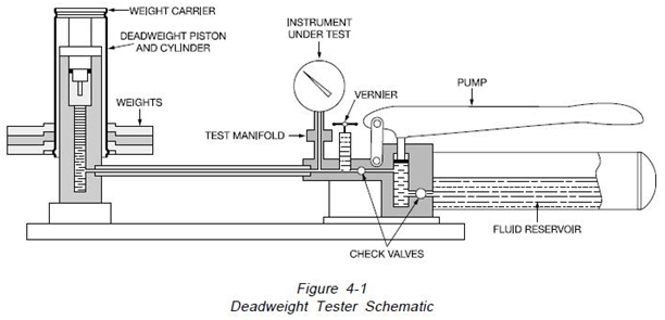
The AMETEK hydraulic deadweight testers are shown schematically in Figure 4-1. These instruments consist of a re-entrant type piston and cylinder mounted in a pressure-containing column assembly, a weight carrier suspended on the piston, weights, a pump to supply pressure and a vernier assembly.
AMETEK hydraulic deadweight testers and deadweight gauges combine several features which are designed to improve the performance and safety of these instruments:
Dual Volume Hand Pump
The lever action hand pump that is supplied with both the Type R & T Hydraulic Deadweight Testers incorporates a dual volume control valve. This permits the pump to deliver a high volume to rapidly fill systems and build pressure. The low volume permits easy pumping at high pressures and a more gradual approach to the point of the pressure calibration.
Overhung Weight Carriers
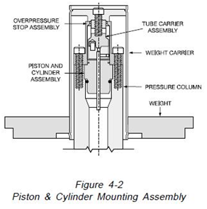
The weights are suspended from a weight tube which is suspended from the piston assembly.
As shown in Figure 4-2, this design lowers the center of gravity of the suspended weights and reduces side thrust and friction on the measuring piston and cylinder assembly thus improving the measurement accuracy.
Re-entrant Type Cylinder and Piston Assembly
This design of the piston and cylinder, as described in Section 2.1.2, has a reduced clearance between the piston and cylinder at higher pressures. The advantage of this design is to reduce the rate of fluid leakage at high pressures, thus increasing the time available for the technician to calibrate instruments prior to pumping to restore fluid loss
Enclosed Piston & Cylinder Assembly
The piston and cylinder assembly is enclosed in a unique column design, see Figure 4-2. The weight carrier is floated on the piston assembly to prevent side thrust. These features prevent accidental damage to the piston assembly.
Positive Over-pressure Protection of the Measuring Piston Assembly
The vertical movement of the measuring piston assembly is restricted by a positive stop as illustrated in Figure 4-2. This positive stop will prevent the piston from damage caused by accidental removal of the weights when pressurized. These stops are rated at the maximum tester pressure.
Interchangeable Piston & Cylinder Assemblies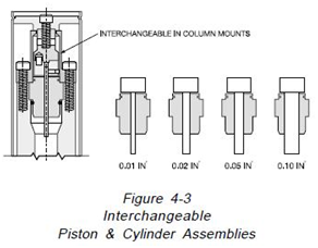
The column assemblies will accept several different size cylinder and piston assemblies as illustrated on Figure 4-3. The Type T or R column accepts piston and cylinder assemblies with cross section areas of 0.1, 0.05, 0.02 and 0.01 square inch. The Type HL column accepts cylinders and piston with square inch areas of 0.1 and 0.02. With the use of a single weight set, this feature increases the test pressure range capability of the testers.
Pressure Vernier
An auxiliary screw-type piston on the Type T & R deadweight testers permits fine adjustment of pump pressure. The pump in the Type HL deadweight testers is a screw-type piston pump that permits fine adjustment.
Accuracy
The standard accuracy of the Type T, R & HL deadweight testers is +0.1% of the indicated pressures at nominal readings. An optional accuracy of +0.025% of the indicated reading is available on the T & R testers.
Certification of Traceability and Accuracy
A certification of traceability and accuracy to NIST’s comprised with each deadweight tester. A certification of accuracy with mass, area, pressures, and intrinsic correction factors that are optional is provided with the optional +0.025% accuracy.
Weight Materials
The weights for all AMETEK deadweight testers are manufactured of non-magnetic materials to prevent inaccuracy. The standard model T, R, 10 and HL weights are manufactured of a hard non-magnetic zinc alloy. Optional weights for the Model T & R testers are made from forged brass conforming to the material requirements of NIST Class Q.
Interchangeable Weights
The weights for standard accuracy (0.1%) deadweight testers are interchangeable and lost or damaged weights may be replaced.
Test Fluid
The test fluid for Type T is distilled water. The test fluid for the Types R, 10 and HL is AAA tester oil.
4.2.1 AMETEK Type T & R Hydraulic Deadweight Testers
The AMETEK Type T & R are pictured in Figure 4- 4. These are high accuracy pressure standards designed for both laboratory and portable use. Specifications and features of these testers are as follows:
Pressure Range: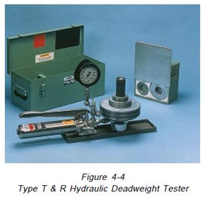
Type T- 10 to 15000 PSI (0.7 to 1034.3 bar)
Type R- 10 to 10000 PSI (0.7 ti 689.5 bar)
Pressure Increments:
High range 50 PSI (3.5 bar)
Low range 5 PSI (0.4 bar)
Standard Models:
Type T- 11 English, 6 metric
Type R- 11 English, 6 metric
Accuracy:
+0.1% of indicated reading
+0.025% of indicated reading (optional)
Features:
- Dual Volume Hand Pump
- Overhung Weight carriers
- Re-entrant type Piston and Cylinder Assemblies
- Enclosed Piston and Cylinder Assembly
- Positive Over-pressure Protection of the Piston Assembly
- Interchangeable Piston & Cylinder Assemblies
- Interchangeable weights on standard accuracy testers
- Pressure Vernier
- Test Fluid- Type T, Distilled Water or AAA oil; Type R, AAA oil
4.2.2 AMETEK Type 10 Hydraulic Deadweight Tester
The AMETEK Type 10 hydraulic deadweight tester is illustrated in Figure 4-5. This tester is designed for both laboratory and portable applications. Specifications and features are as follows:
Dual Pressure Range: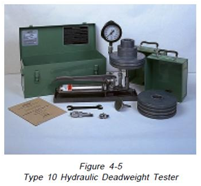
5 to 2000 and 25 to 10000 PSI
(0.4 to 138 and 1.7 to 689.5 bar)
Pressure Increments:
High range 25 PSI (1.7 bar)
Low range 5 PSI (0.4 bar)
Standard Models:
5 English, 10 metric
Accuracy:
+0.1% of indicated reading
Features
- Interchangeable coaxial design piston and cylinder assemblies for rapid changeover.
- Interchangeable weights
- Single volume pump
- Simple Piston and Cylinder assembly
- Pressure Vernier
- Test Fluid, AAA oil
4.2.3 AMETEK Type HL Hydraulic Deadweight Testers
The AMETEK Type HL, Hydra Lite, the hydraulic deadweight tester is illustrated in Figure 4-6. This tester incorporates a unique single-case design for portable applications. The entire tester, including weights, is contained in a 9.0 x 9.0 x 10.0- inch (228.6 x 228.6 x 254.0 mm) case. Specifications and features are as follows:
Dual Pressure Range: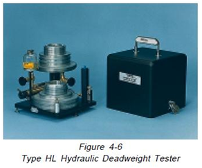
10 to 600 and 50 to 3000 PSI
(0.7 to 41.4 and 3.5 to 206.9 bar)
Pressure Increments:
High range 0.5 PSI
Low range 0.1 PSI
Standard Models:
9 English, 18 metric
Accuracy:
+0.1% of indicated reading
Features
- Test fluid, AAA oil
- Positive over-pressure protection of the measuring pistons
- Cylinder assembly and enclosed piston
- Re-entrant type cylinders and piston
- Overhung weight carriers
- Tripod mountable for field use
- Interchangeable weights
- Screw type single piston pump using a ratchet handle
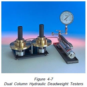
4.2.4 AMETEK Dual Column Hydraulic Deadweight Tester
The AMETEK dual column hydraulic deadweight testers are illustrated in figure 4-7. These testers, which are manufactured in both Type T and Type R designs, are designed for both laboratory and shop installation. Separate columns are provided for both the high and low pressure piston and cylinder assemblies. Range changes are accomplished rapidly by actuating a crossover valve.
The features and specifications are identical to the Type T and Type R described in paragraph 4.2.1.
4.3 Features of AMETEK Hydraulic Piston & Cylinder Deadweight Gauges
A deadweight gauge is designed to be connected to a source of pressure, such as a feed water line in a steam power plant or a gas well head, and measure the pressure with a high degree of accuracy. In operation, after the tester is connected to the pressure source, weights are added onto the piston until the piston floats freely in mid-stroke. The features of the deadweight gauges are identical to the comparable deadweight testers (Type T and Type HL) with the following additions:
- Elastomer Membrane Fluid Separator
An elastomer membrane is included to permit isolation of the piston and cylinder from the process fluid to permit operation with both contaminating and abrasive fluids and also to permit operation with pneumatic pressure.
- Conversion Capability to a Deadweight tester
The Type HLG may be converted to a deadweight tester with the addition of a conversion kit.
4.3.1 AMETEK Model HLG Deadweight Gauge
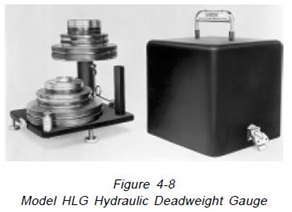 The AMETEK Model HLG deadweight gauge’s indicated on Figure 4-8. This instrument’s made as an instrument that’s portable to accurately take pressure measurements under field conditions. The range and features are identical to the Type HL deadweight tester. This instrument can be upgraded to a Model HL deadweight tester by adding an AMETEK conversion kit (P/N T-535).
4.4 Features of AMETEK Floating Ball Type
Pneumatic Dead Weight Testers
The AMETEK pneumatic deadweight testers are pressure standards that are self-regulating primary type.
An accurate calibrating pressure is produced by bringing into equilibrium the pneumatic pressure on the under-side of the ball with known effective area by weights of known mass on the top.
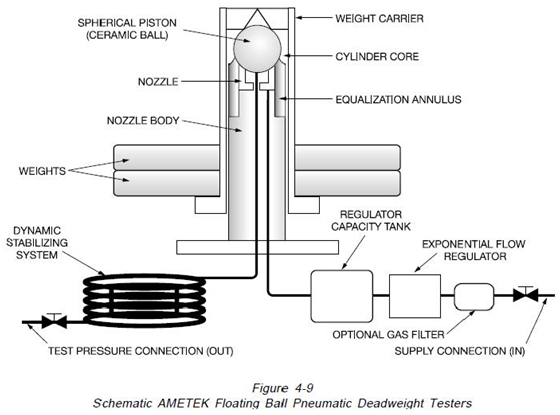
The ball type pneumatic deadweight tester’s indicated on the schematic diagram on Figure 4-9. In this type of construction, a precision ceramic ball is floated within a tapered stainless steel nozzle. A flow regulator produces pressure under the ball, lifting it in the stainless steel nozzle until equilibrium is reached. At this point, the vented flow and the ball floating equals the fixed flow from the supply regulator. The pressure, which is also the output pressure, is proportional to the weight load. During operation the ball is centered by a dynamic film of air, eliminating physical contact between the ball and nozzle.
When weights are added or removed from the weight carrier, the ball rises and lowers, affecting the air flow. The regulator senses the change and adjusts the pressure under the ball to bring the system under equilibrium, changing the output pressure accordingly. This regulation of output pressure is automatic with changes in weight mass on the spherical piston (ball). When minimum supply pressures are maintained, the unit equilibrium is unaffected by variations in supply pressure.
AMETEK floating ball type pneumatic dead weight testers combine several features which are designed to improve the performance and safety of these instruments:
Floating Ball
During operation, the weights and ball float freely, supported by only a film of air which is virtually frictionless. This feature eliminates the necessity to rotate the weights during testing, thus the technicians are freed and can concentrate on the instrument calibration task.
Self Regulating
The built-in flow regulator automatically adjusts the input air flow to maintain the ball and weights
in a float position. The regulator also compensates for variations in pressure from the air supply. These features eliminate the necessity of the technician continually adjusting the supply during the test, thus permitting the technician to calibrate instruments more efficiently.
Rugged Ceramic Measuring Ball
The piston/floating ball is made from aluminum oxide ceramic. This material has near diamond hardness. Unlike carbide pistons and steel, the ball can be dropped on hard surfaces without damage.
Quick Setup and Operation
Set up is completed by connecting two tubes and adding the appropriate weights. Operation is fast with no valves to adjust or regulate between set points. Pressure regulators are not required if the air supply is within the tester’s operational requirements.
Non Contaminating Test Fluid
The test fluid is nitrogen or instrument quality air complying with the ISA Standard S7.3. This fluid is non contaminating to virtually all processes, thus eliminating the need to clean instruments after calibration before use.
Tripod Mounting
The Models PK II and RK are designed for both laboratory and portable use. Both instruments incorporate built-in tripod mounts.
Closed Cover Operation
The Model PK II is designed to operate with the cover closed, thus eliminating the effects of wind during outside portable operation.
Ball Valves
All of the AMETEK floating ball testers combine multi-position ball valves for both the inlet and outlet valve connections. These valves afford quick, easy and trouble- free operation.
Pre-fill Valve
A pre-fill valve connection is provided on the Model HK high pressure pneumatic testers. This valve permits the inlet pressure to bypass the flow regulator to permit rapid filling of the system volume to be tested.
Accuracy
The standard accuracy of the Models PK II and RK is +0.05% of the indicated pressures at nominal readings. Optional improved accuracies of +0.025% and +0.015% of the indicated pressures at nominal readings are available.
The standard accuracy of the Model HK tester is +0.025 % of the indicated pressure or +0.025 PSI whichever is greater.
Gravity
Standard weights for all of the ball type deadweight tester models are manufactured from non-magnetic 300 series stainless steel. These weights can be calibrated to operate at International Standard Gravity (980.665 Gals.) or at the customers’ local gravity.
A PK II tester’s economic model is available with cast weights. The weights of these are calibrated to U.S. Mean Gravity (980.000 Gals.)
Certification of Traceability and Accuracy
A certification of traceability and accuracy to NIST’s comprised with each floating ball type deadweight tester. A certification of accuracy (that’s optional) with available mass, area as well as intrinsic correction factors.
Weight Materials
The weights for all floating ball pneumatic deadweight testers are manufactured from non-magnetic materials to prevent inaccuracy. The standard Model PK II, RK, and HK weights are manufactured from 300 series stainless steel. The economic Model PK II uses cast weights manufactured of a hard nonmagnetic zinc alloy.
Interchangeable Weights
The cast weights for the economy Model PK II tester are interchangeable and lost or damaged weights may be replaced. AMETEK maintains a permanent file on all deadweight testers. All damaged or lost stainless steel weights can be replaced with the original mass when manufactured. In most instances, it is recommended that these testers be recalibrated prior to weight replacement.
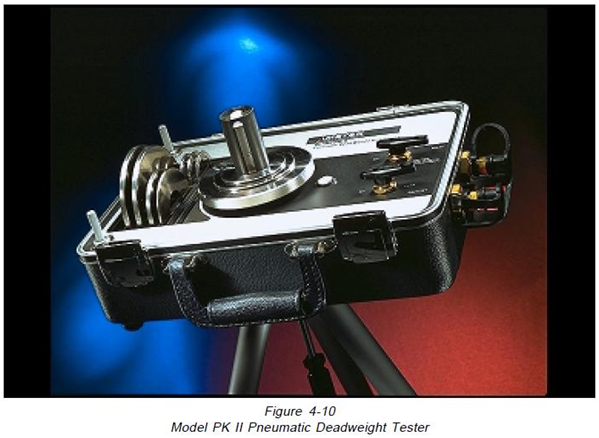
4.4.1 AMETEK Model PK II Portable Deadweight Tester
The AMETEK Model PK II floating ball deadweight testers are pictured on 4-10. These instruments are high accuracy instruments designed for both laboratory and portable operation. This instrument is self-contained in a rugged ABS plastic case designed for “Closed case operation”, eliminating wind problems. The weights are individually stacked vertically in pockets in the case for ease of operation. Specifications and features of these testers are as follows:
Pressure Range:
4″ H2O to 30 PSI
Standard Models:
10 English, 5 metric
Accuracy:
+0.05% of indicated reading
+0.025% or +0.015% of indicated reading (optional)
Features
- Interchangeable Weights on Economical Model Tester
- Stainless Steel weights Calibrated to
- Local or International Standard Gravity
- Ball Valves for Inlet and Outlet
- Closed Cover Operation
- Tripod Mount is Standard
- Non -Contaminating Test Fluid
- Quick Setup and Operation
- Rugged Ceramic Measuring Ball
- Self Regulating
- Floating Ball
4.4.2 AMETEK Model RK Portable Floating Ball Deadweight Tester
The AMETEK Model RK floating ball deadweight testers are pictured in Figure 4-11. These instruments are high accuracy instruments designed for both laboratory and portable operation. This instrument is self-contained in a cast metal base with an ABS plastic cover. It is self-contained with weights for pressures to 50 PSI (3.5 bar), with additional cases to carry the remaining weights. The weights are stacked vertically in the cases for ease of operation. Specifications and features of these testers are as follows: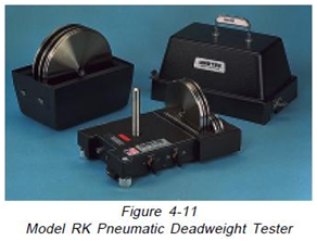
Pressure Range:
4″ H2O to 300 PSI
Accuracy:
+0.05, +0.025% or +0.015% of indicated reading
Repeatability:
+0.005% of output reading
Temperature Coefficient:
0.00167% output pressure per °C
Models
10 English, 15 metric
Features
- Floating Ball
- Self-regulating
- Rugged Ceramic measuring ball
- Quick Setup and Operation
- Non- Contaminating Test Fluid
- Tripod Mount is Standard
- Ball Valves for Inlet and Outlet
- Stainless Steel Weights
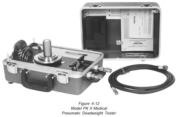
4.4.3 AMETEK Model HK High Pressure Floating Ball Deadweight Tester
The AMETEK Model HK floating ball pneumatic deadweight testers are pictured in Figure 4-12.
These instruments are high accuracy instruments designed for laboratory operation. All instruments are supplied with stainless steel weights with a protective storage case. The tester itself is supplied with a laminated wood grained storage case. Specifications and features of these instruments are as follows:
Pressure Range: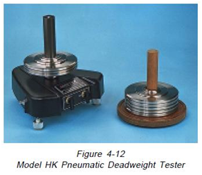
Standard 10 to 1000 PSI (0.7 to 69 bar)
Optional 100 to 1500 PSI (6.9 to 103.4 bar)
Accuracy:
+0.025% of indicated reading
Repeatability:
+0.005% of Output Reading
Temperature Coefficient:
0.00167% output pressure per °C
Models
5 English, 3 metric
Features:
- Stainless Steel Weights Calibrated for Local International Standard Gravity
- Pre-fill Valve
- Ball Valves for Inlet and Outlet
- Non -Contaminating Test Fluid
- Quick Setup and Operation
- Rugged Ceramic Measuring Ball
- Self Regulating
- Floating Ball
4.4.4 AMETEK Model PK II Medical Floating Ball Deadweight Tester
The AMETEK Model PK II Medical floating ball deadweight tester, indicated on Figure 4-12, is a primary type, portable, self-regulating, pressure standard designed to provide an accurate pressure calibration standard for physiologic pressure ranges. Standard hospital wall oxygen outlets or therapeutic oxygen pressure regulators provide a convenient source of supply pressure. The instrument will also operate on compressed air or dry nitrogen. Specifications and features of these testers are as follows:
Pressure Range:
10 to 325 mm Hg
Accuracy:
+0.05%, +0.025% or +0.015% of Indicated Reading
Repeatability:
+0.005% of indicated reading
Temperature Coefficient:
0.00167% of output pressure per °C
Features
- Stainless Steel Weights Calibrated to Local or International Standard Gravity
- Oxygen Swivel Valve and Hose on
Inlet, 1/8″ Male Luer Lock on Outlet - Closed Cover Operation
- Non-Contaminating test fluid
- Quick Setup and Operation
- Rugged Ceramic Measuring Ball
- Self-regulating
- Floating Ball
4.5 Care of AMETEK Deadweight Testers
4.5.1 Care of AMETEK Cylinder & Piston Type Deadweight Testers
The United States National Institute of Standards and Technology has suggested that “For use of piston gages as laboratory standards or plant (Accuracy within 0.1%), the following points are pertinent to the instrument performance:
1.The weights should be non-magnetic, solid, preferably of hard, nonporous metal, such as brass or stainless steel. They should mesh accurately, and should have a smooth finish, preferably polished.
2. The piston should turn freely in the cylinder.
When the weights are loaded on top of the piston and set into rotation, they should continue to rotate for several minutes. Some instruments have means for oscillating or rotating the piston.
These devices should create negligible longitudinal thrust.
3. When the gauge is connected to a leak-tight system, and the piston is set into rotation, the piston must slowly fall due to the leak between it and the cylinder. The fall rate of a good instrument must be under 0.1 inch per minute at maximum pressure. We consider this to be the most significant single index of quality.
4. The structure should be such that the level of oil surrounding the piston is known at all positions of the piston, in order to correct for air buoyancy. The weight of oil displaced by the submerged portions of the piston, and the weight of air displaced by the rest of the piston and load, must be subtracted from the load. The pressure thus measured is that which obtains at the level of the oil surface. If the reference level of the gauge being calibrated is higher or lower at this level, corrections should be made for the head of oil, about 0.03 PSI (2 mbar) for each inch of difference in height.
5.Occasionally the direction of rotation will affect the pressure developed by the piston gauge. This has been attributed to helical tool marks on the cylinder or piston or guide bearing. Observations must at least be taken occasionally, reversing the direction of rotation, but changing nothing else.
6.Erratic behavior has sometimes been observed in case the weights are really stacked off center. There could be pressure fluctuation in synchronism with the rotation, or a change of pressure which depends on the speed of rotation or a change of pressure which depends on the speed of rotation, but not the direction. These problems are most severe in instruments with the weights stacked in a tall pile on top of the piston. A suspended, non rotating load may oscillate abnormally when the piston is oscillated or rotated at a certain speed. Such speeds must be avoided.”
AMETEK has found the following items to be important factors affecting the performance and life of piston gauges:
1. FLUID CLEANLINESS-Deadweight testers are devices that are closely fit with clearances of 1 or 2 millionths of an inch and finishes exceeding 1 micro inch. The principle source of fluid contamination is the interior of instruments being calibrated. When pressure is relieved, contaminants within the instrument being calibrated are exhausted into the deadweight tester. If instruments contain dirty fluid or particles, they should be flushed prior to testing. Individual users must consider the cleanliness of the instruments when establishing the frequency of changing the test fluid.
2. FLUID LUBRICITY-The test fluid creates a lubricating film between the closely fit piston and cylinder. The ability of the fluid to lubricate at high pressure is an important criterion in determining the wear rate of cylinders and pistons. A high-pressure spindle type oil like AMETEK AAA Tester Oil provides maximum protection. Other test fluids such as water which is used within the AMETEK Type T testers afford satisfactory operation but reduce service life slightly. Silicone oils must be avoided as they tend to crystallize at high pressures causing the piston and cylinder to seize.
3. STORAGE TECHNIQUES-The storage of the close fitting cylinder and piston assembly’s important to service life that’s continued. AMETEK has found that the piston and cylinder should be separated and individually coated with light oil during storage. After storage, both the piston and cylinder must be cleaned before use.
4. INSTALLATION-It’s important to install the piston and cylinder so that the piston does not bind within the cylinder. The cover that secures the piston and cylinder within the AMETEK Type T & R testers has 8 cap screws. These screws should be tightened in a criss-cross pattern to reduce distortion. Regular changes of the cylinder and piston should be avoided because of the attendant risk of damage. If the user’s task involves frequent calibration of instruments, the AMETEK Dual Column Assembly must be considered. in this device, the high and low pressure pistons are mounted separately and range changes are accomplished by adjusting the high pressure valves.
5. CLEANING-The most important care that can be given to a deadweight piston and cylinder assembly is cleaning. Cleaning is particularly important during the initial use of pistons and cylinders. Although efforts are made to clean all parts after manufacture, some abrasive particles remain within the pores of the material. After the application of pressure, these particles are discharged. It is recommended that new pistons and cylinders be cleaned prior to each use for the first month of operation. Monthly cleaning thereafter is satisfactory. AMETEK recommended cleaning procedures are included in paragraph 4.6.1.
4.5.2 Care of AMETEK Floating Ball Type Pneumatic Deadweight Testers
AMETEK has found the following items to be important factors affecting the performance and life of the floating ball type pneumatic deadweight testers.
1. AIR CLEANLINESS-The AMETEK floating ball deadweight tester contains several small diameter bores. Free passage of air within these bores is important for the correct operation of this device. The air used to operate the tester must be both clean and dry to preclude problems. M&G recommends the use of instrument quality air as defined by Instrument Society of America Specification ISA-S7.3 “Quality Standard for Instrument Quality Air”.
2. CLEANING-Cleaning of the ball and nozzle is important prior to the use of the pneumatic dead weight tester. This cleaning is easily done by removing the tester nozzle and cleaning the nozzle, nozzle body, and ball with a non-residue solvent such as grain alcohol and a lint-free cloth or paper. Tester weights should be cleaned periodically with alcohol and a lint free cloth or tissue paper.
3. LEVELING-For proper operation, the air stream exhausting around the ball should be equally distributed around the periphery of the ball and the weight carrier is not in any contact with the nozzle body. Each tester is equipped with a bullseye level which is preset during manufacture. A proper level may be verified by either of the following methods:
A. The tester should be leveled and operated only with the weight carrier (4″H2O or 10″H20) in place. The carrier should be carefully set into rotation. The rotation must continue for two (2) minutes at least. If the rotation stops prematurely, the level should be corrected.
B. The hand may be placed above the nozzle and feel the direction of the exhaust gas. This stream should be approximately vertical when the tester is in operation. The weight carrier may be rotated to aid in the determination of the air stream direction.
It should be noted that once the tester is calibrated and the level is adjusted, the level should not be reset unless the accuracy of calibration is retested.
4. OPERATING TECHNIQUE-The pneumatic deadweight tester is designed as a self-regulating device that produces an accurate pressure independent of operator technique. The operator must, however, exercise care during operation. The weight carrier is suspended from the ball on three prongs. Care should be taken not to drop weights or drop the carrier onto the carrier in ways to bend 1 or more prongs.
5. LEAKAGE- The accuracy of the pneumatic tester is seriously affected by leaks in the output or input connections and/or within the instrument being calibrated. Leaks within the output connection or instrument are easily determined by closing the tester output valve and deciding if the instrument that’s under test indicates pressure loss. Internal tester leaks are identified by placing an O-ring under the ball and closing the pressure inlet. Again, pressure loss indicated on the instrument being calibrated indicates a leak.
6. TEST GAS-The pneumatic deadweight tester is calibrated for pressure accuracy with nitrogen gas. The use of gases with other densities will affect the output pressure. The testers can be calibrated for some gas densities other than nitrogen on special order. Gases used with the tester must also be compatible with the materials used for construction. AMETEK can assist users, on request, to assess alternate gases.
4.6Procedures for the AMETEK Deadweight Testers Use
4.6.1 Procedures for Cleaning Hydraulic Cylinders and Pistons
Each cylinder and piston must be cleaned before use. If a piston and cylinder has been stored outside the tester, it should be recleaned prior to use. It is very important that new cylinders and pistons be repeatedly cleaned before use to remove all evidence of the abrasive particles used during manufacture. Periodic recleaning of piston and cylinders is necessary. A lack of sensitivity to small pressure changes is an indication that cleaning is necessary.
The recommended cleaning procedure for cylinders and pistons is as follows:
1. Carefully wipe off any foreign matter or visible dirt from the piston’s protruding part and withdraw the piston slowly from the cylinder. Do n’t use force, but ensure that every dirt is removed in order for the piston to be slipped out easily.
2. Boil both the piston and cylinder for at least 15 minutes in distilled water. The cylinder bore must be wiped using a small wood handled wiper like a cotton swab to get all evidence of dirt removed. Wipe the piston clean and dry with a lint- free tissue paper.
3. Rinse both the piston and cylinder in grain alcohol.
4. Wipe the cylinder bore and the piston again to remove any dirt or grit.
5.Pick up the piston by the piston cap and dip it into a clean fluid to be used in the tester, then carefully insert the piston into the cylinder. If any feeling of roughness or what might be grit in the annulus area is suspected, then disassemble and repeat the cleaning procedure.
6.At the same time, the deadweight column output post and tubing should be drained and flushed with a residue-free solvent such as grain alcohol, then cleaned, dried, and refilled with clean test fluid.
7. Then, the cylinder and piston assembly can be installed carefully in the mounting column.
CAUTION
After cleaning, don’t touch the cylinder and piston with fingers or other contaminating or soiled surfaces. Extremely minute particles may create trouble in a closely fitted assembly.
4.6.2 Procedures for the Use of Hydraulic Deadweight Testers
The following procedure is typical of methods used to test pressure instruments using hydraulic deadweight pressure testers. The user is encouraged to modify these procedures to test critical instrument characteristics.
The step- by -step procedure is as follows:
1. Remove the pressure instrument from service and blowdown (Vent to atmosphere to remove trapped pressure from the pressure side of the instrument).
2. Set up the deadweight tester and level the instrument.
3. Connect the pressure input of the pressure instrument to the pressure test port on the deadweight tester.
4. Put weights on the deadweight tester carrier equal to 90 to 100% of the range of the instrument being tested.
5.Build up the pressure with the tester hand pump until the weights freely float. Have the weights rotated from 10 to 30 RPM. Check to ensure that leaks are not present.
6.If leaks are not present, carry out with the calibration. If leaks are visible, they should be located and repaired before proceeding with the calibration.
7.Remove all pressure from the tester hand pump. Vent the high and low side of the pressure instrument to atmosphere. On the instrument, adjust zero.
8. Leave the low side of the instrument open to atmosphere; open the high side of the instrument to the deadweight tester.
9.Start calibration by adding weights on the deadweight tester weight carrier that are equal to 25% of the instrument range being tested.
10.Build up pressure with the tester hand pump until the weights freely float. Have the weights rotated from 10 to 30 RPM. Let the instrument settle for one (1) minute. Tap the case of the instrument.
Record the reading.
11.Place additional weights on the deadweight tester to read points at 50%, 75%, and 100% of the instrument range.
12. Close the valve between the instrument being tested and deadweight tester.
13. Remove weights from the deadweight tester to read 75% of the range of the instrument being tested.
14.Open the valve between the instrument being tested and the deadweight tester. Allow the deadweight tester weights to settle. Weights should be freely floating and have a rotation of 10 to 30 RPM. Allow the tester to stabilize for one (1) minute. Tap the case of the instrument. Record reading.
15. Repeat steps 12 through 14 to read points at 50% and 25% of the instrument range.
16. Remove all pressure from the instrument being tested. Recheck the zero on the instrument.
4.6.3 Procedures for the Hydraulic Deadweight Gauges Use
Deadweight gauges are utilized to make measurements on pressures contained with high precision in an external source. Deadweight gauges don’t have a pump or any pressure’s self-contained source.
It’s vital to emphasize that all chambers, fittings, and tubing within the gauge of the deadweight be rated at pressures that are higher in comparison to the pressure source that could be attached to the gauge. Deadweight testers must not be utilized as deadweight gauges except if it’s certified by the manufacturer.
The following procedure is typical of the methods used for hydrostatic testing on pipelines and well static pressure testing.
The step-by-step procedure is as follows:
1. Set up the deadweight gauge and level the instrument.
2. Connect the pressure port on the device to be tested to the inlet port of the deadweight gauge.
A shut-off valve should be placed at the pressure port and at the inlet of the deadweight gauge. A separator may be connected between the pressure tap and the inlet of the deadweight gauge. Some deadweight gauges have isolation devices in order to prevent contamination from getting in contact with the cylinder and piston (See 4.3.1 , Elastomer Membrane).
3.On the deadweight gauge inlet, shut the valve, and open the valve on the pressure port. Check for leaks; if leaks are present, they must be repaired before proceeding, if no leaks are present proceed with the test.
4.Place weights on the deadweight gauge equal to 100% of the pressure within the line or well to be tested.
5.Slowly open the inlet valve to the deadweight gauge. Have the weights rotated from 10 to 30 RPM.
6. Watch the direction of the float of the cylinder and piston. If the piston’s falling, the weight should be removed. If the piston’s rising, weight must be added. Weights must be deleted or added until equilibrium within the mid one-third of the cylinder and piston float range is accomplished.
7. Sufficient time must be allowed for pressure conditions to stabilize. The higher the pressure the longer the period required for the conditions to stabilize.
8.Close the valve on the pressure port on the device being tested. Have the deadweight gauge vent valve opened to relieve pressure. Close the input valve on the deadweight gauge.
9. Remove the weights on the deadweight gauge. Use the manufacturer’s data to determine the measured pressure. For example:
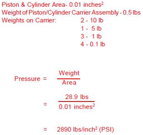
10.The pressure measured by a piston gauge loaded with a particular value of weights is proportional to the local value of gravity. Once the local value of gravity is known (See paragraph 1.4), the nominal values could be converted to actual values via the equations below:
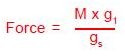
Where:
M = Mass
gl = Local value of gravity in cm/sec2
gs = 980.665 (International Standard Gravity)
Under standard conditions, the pounds weight is equal to the pounds mass.
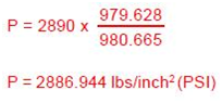
Continuing the example:
Local Gravity = 979.628 Gals (cm/sec2)
Calibrated Gravity of Deadweight Gauge
Weights = 980.665 Gals.
4.6.4 Procedures for the Use of Floating Ball Type Pneumatic Deadweight Testers
A suggested step- by step procedure to be used when calibrating a flow measuring instrument (Meter) with a PK tester is as follows:
1. Remove meter from service and blowdown.
2.Level PK and connect the gas supply (30-35 PSIG) to the inlet of the PK. PK should be close to the meter to eliminate the long tubing line on the outlet. (Be sure the skirt of the weight table is not dragging on the nozzle body.)
3.Connect the PK outlet to the high side of the meter. Vent the low side of the meter to atmosphere. Turn on the supply gas to the PK and open the outlet valve. provide filtered gas that’s free of liquids.
4. Put weight equal to above 90% to 100% of the meter range of the PK and allow the pen to travel to a full stop on the chart (At least one minute).
5. Close the outlet of the PK and observe the reading on the chart for about two or more minutes.
6. If no leaks are present, proceed with the calibration. If leaks are present they must be located and repaired before proceeding with the calibration.
7. With the PK outlet valve closed, vent the high and low side of the meter to atmosphere and adjust the zero on the chart.
8. Leave the low side of the meter open to atmosphere, connect the high side to the PK.
9.Start meter calibration by having the table and the necessary weights placed on the PK to read about 6″ on a 50″ meter (12″ on a 100″ Meter). Allow meter and PK to settle in for at least one full minute minimum time before pulling the point on the chart. (Note: Use weights that allow reading to fall on the narrow line of the calibrating chart)
10.Place additional weights in increments of 10″ on the table in order to read points at 16″,26″, and 46″ on a 50″ meter (32″, 52″, 72″, and 92″ on a 100″ meter, etc). Care must be taken when putting weights on the table to see that all points are reached with the meter traveling in the up direction, in other words, do not overshoot the points. Again, wait a minimum of an entire 1 minute prior to pulling any points.
13.Check down points at 42″, 32″, 22″, and 12″ on a 50″ meter (84″,64″,44″, and 24″ on a 100″, etc.). Care should be taken to remove weights in the proper manner so that all down points are reached from the downward travel of the meter. This is important as it will tell if there are binds in the meter.
14. Recheck zero of the meter.
Source: Ametek