Deadweight Tester Calibration
Deadweight testers can be calibrated using either the “Fundamental” or “Calibrated” methods to measure the pressure and effective area. A fundamental calibration involves having the effective area of the gauge determined using only measurements of the SI base units (e.g. mass, length) plus a suitable model. A calibrated calibration has the effective area determined via calibration against a gauge for which the effective area or generated pressure is already known.
3.1 Methods of Calibration
3.1.1 Fundamental Characterization of Deadweight Testers
The dimensional characterization of both the piston and cylinder are usually performed under conditions of atmospheric pressure and room temperature. Depending upon the shape of both the piston and the cylinder and the support structure for the mass loading mechanism, the detailed dimensional characterization is usually confined to that part of the piston that is inside the cylinder during normal operation. Pistons of unusual shape are not normally characterized using this technique.
 Once a set of dimensional measurements has been performed on both the piston and cylinder, there are several ways in which the area of both the piston and cylinder can be specified. Depending upon the severity of the departure of the piston surface from true cylindricity, an average radius of the piston and cylinder may be calculated, or more sophisticated approaches including distortion of the piston by the applied pressure and thermal expansion of the piston can be applied. The overall area of the piston and cylinder assembly is then computed using an appropriate mathematical model.
This technique is used primarily by national standards laboratories, such as the National Institute of Standards and Technology that are responsible for establishing reference measurements for a larger group such as the United States.
3.1.2 Calibrated Characterization of Deadweight Testers
The calibrated characterization of deadweight testers involves the transfer of effective areas of one piston and cylinder to another utilizing pressure based cross-float techniques. To use this technique, identical piston and cylinders are placed in identical mountings with the output pressures connected. Means, such as a differential pressure meter are included to identify the time when a pressure balance between the two pressure generating components has been achieved at the reference levels of both the test and reference units. During the test the weights are exchanged on the columns and the piston and cylinders are exchanged in the mountings to reduce the uncertainty of measurement. This technique is used primarily by industry and calibration laboratories.
The reference or master pressure generating units (Piston-Cylinder & Weights) are usually tested at a standards laboratory (AMETEK masters are tested at NIST).
3.2 Test Equipment for Pressure Standards Laboratory
Many different combinations and assemblies of equipment may be utilized with varying degrees of uncertainty of measurement (See paragraph
2.2). We will use for purposes of illustration, the equipment that is used within the AMETEK Pressure Standards Laboratory.
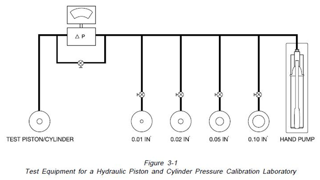
3.2.1 Hydraulic Piston-Cylinder Deadweight Testers
The equipment, as illustrated on Figure 3-1, consists of four identical column assemblies to hold the master piston and cylinders and one identical column to hold the piston and cylinder under test. Each of the master columns contains a master piston of a single range (0.01,0.020,.05,0.1in2) to minimize disassembly after calibration. Master weights with known mass are used on both the test and master piston and cylinders. An analog differential pressure meter is used to indicate when a pressure balance is achieved. A crossover valve permits interconnection of the output pressure generating components. The pressure balance is illustrated by the following equation: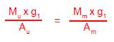
Which simplifies to:
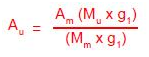
Where:
Au = Area of the unknown piston and cylinder
Am = Area of the master piston and cylinder
Mt = Known mass of the test weights
Mm = Known mass of the master weights
g1 = Local gravity
The procedure for calibration of a piston and cylinder with an unknown effective area consists of the following steps:
1. The unknown piston and cylinder is cleaned and installed in the test column.
2. Pressure is applied to both the unknown piston and cylinder and the master piston and cylinder to bring both pistons to position in the middle of the vertical float range.
3. Both pistons are rotated approximately 30 RPM and the cross-over valve is closed.
4. The pressure differential between the master and the test piston-cylinders is indicated on the null meter.
5. Tare weights are added to the piston-cylinder that is low in pressure until the null meter shows a pressure balance. The required tare weights are recorded on the test log.
6. A small tare weight is placed upon the opposite piston and cylinder to unbalance the pressure to the opposite side. This test assures that the piston was free and sensitive when the pressure balance was measured.
7. The steps 2-6 are repeated for each required test pressure.
8. The effective area of the unknown piston and cylinder is determined using the equation in paragraph 2.4 (AMETEK uses a proprietary computer program for this task).
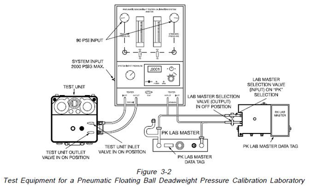
3.2.2 Pneumatic Floating Ball Deadweight Testers
The equipment, as illustrated on Figure 3-2, consists of an AMETEK Pneumatic Tester Calibration System, a master floating ball pneumatic tester, with a known effective area, of the identical design (Model PK or RK) as the tester being tested, master weights with known mass and test weights with known mass. The calibration system incorporates a cross-over valve, a digital readout differential pressure meter and input flow meters for both the test and master testers.
The procedure for calibrating the floating ball testers is as follows:
1. The ball, nozzle and nozzle body of the floating ball tester with unknown effective area are thoroughly cleaned
2. The tester is leveled and he bulls-eye level is adjusted accordingly (See Section 4. for the recommended procedure for leveling).
3. Input pressure is applied to both testers with the cross-over valve in the open position.
4. Weights are added to both the test unit and the master unit for the initial test point.
5. The cross-over valve is closed. The pressure differential between the test and
the master tester is displayed on the differential pressure meter display.
6. The steps 3 and 4 are repeated for each required test pressure.
7. The effective area of the unknown ball and nozzle is determined using the equation in paragraph 2.4 (AMETEK uses a proprietary computer program for this task).
3.3 Frequency of Calibration
3.3.1 Frequency of Recertification and Recalibration of Piston & Cylinder Type Deadweight Testers
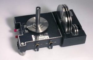
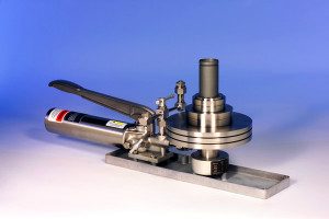
The precision piston and cylinder assembly, the operating heart of the hydraulic deadweight tester, is a device which given proper care and use has a long service life. M&G has many customers who have pistons and cylinders in use for over 10 years.Ametek Type T Hydraulic Pump
 Recertification of a deadweight tester is a precautionary measure required by each user to assure that each device has not worn sufficiently to produce inaccurate pressures. As discussed in paragraphs 2.6.1 and 3.3, many different pressure between the output on the master and factors can contribute to wear of the piston and cylinder. No specific time period for recertification is appropriate for each application. If the device is exposed to heavy usage and factors that contribute to wear such as dirty instruments being tested, frequent calibration is appropriate. Infrequently used instruments used only in laboratory conditions need not be calibrated frequently.
The United States National Institute of Technology has suggested that7″For piston gages for use as plant or laboratory standards (Accuracy within 0.1%) when the gage is connected to a leak tight system and the piston is set into rotation that the piston should fall slowly as a result of the leak between it and the cylinder. At maximum pressure, the fall rate of a good instrument should be less than 0.1 inch per minute. We regard this as the most important single index of quality”.
Confirming the NIST findings, AMETEK has found that the leakage rate of the piston and cylinder is the best measure of wear. This is an easy test to perform on AMETEK testers:
1. Load the tester with 100# of weights.
2. Pump piston to the top of the stroke.
3. Spin the weights and measure the time until the weights descend to the bottom of the stroke.
4. If the time, thus the leak rate, increases significantly (+5%) wear is indicated and the tester should be recalibrated.
AMETEK suggests that for users with unknown history of usage with deadweight testers consider conducting leakage tests monthly and have the testers recertified annually. This annual recertification should include the actual performance data. As the user accumulates a history of usage and wear, the recertification interval can be adjusted accordingly.
3.3.2 Frequency of Recertification of Floating Ball Type Pneumatic Type deadweight Testers
Frequency of recertification of a pneumatic deadweight tester is a precautionary measure undertaken by each user to assure that the device is functioning accurately and has not worn in such a way as to produce inaccurate pressure. As discussed in Section 4.5, many factors can contribute to malfunction and wear. No standard period of recertification is appropriate for every application. If the device is used for portable service in dirty or dusty environment, frequent recalibration is appropriate. Infrequently used instruments used only under laboratory conditions need not be calibrated as frequently.
AMETEK has found that the input flow rate to the tester for a specific output pressure is the best measure of the operation of the tester. A flow meter capable of reading flow in Standard cubic Feet per Hour is placed in the input nitrogen line prior to the tester. The tester is cycled through several output pressures within its pressure range and the input flow rate is recorded. This flow recording should be initiated when the tester is new or immediately after a recalibration is completed. If a flow rate for a given pressure changes significantly (+5%), wear or malfunction are indicated.
Formal recertification should be done at regular intervals by cross-floating the tester against a NIST Certified Master Tester in a pressure laboratory. AMETEK recommends that users with an unknown history of usage with ball type pneumatic testers initially consider conducting flow tests monthly and have the testers recertified annually. The annual test recertification should include performance data (Area, mass, correction factors, etc). As the user accumulates a history of usage and wear, the recertification cycle can be adjusted accordingly.
Source: Ametek